| Thunder Charged! Part 3 The Rejetting – Surgery |
Part Three
Click on a Thumbnail to Enlarge
|
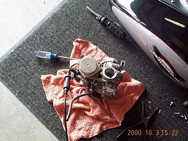
Now that you've had two relaxing and refreshing "coffee breaks", you're ready to tackle the third leg of your quest. This is the carb assembly removed. You will have a couple of hoses still attached to it, along with the choke cables. Treat it gently. NOTE: Do not separate the carbs! If you have previously rejetted and are only changing the main jets for a THUNDER AIR KIT, you will skip the sections covering the needles, slides, and drilling the slide lift holes, as you have previously done this on your initial rejetting. But you will need to drop the needle clips per the Stage 3 Jetting. |
 |
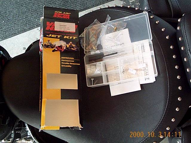
| With your handy dandy brandy newy jet kit, you're ready to perform surgery! |
 |
|
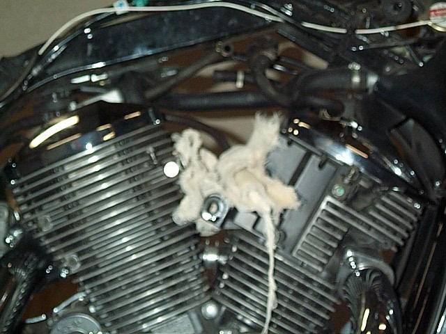
Oh, by the way, make sure you put a rag or something over the cylinder intake ports to keep anything from getting in them. Now's a good time to tell you, huh? My camera must have been getting tired by this point! |
 |
|
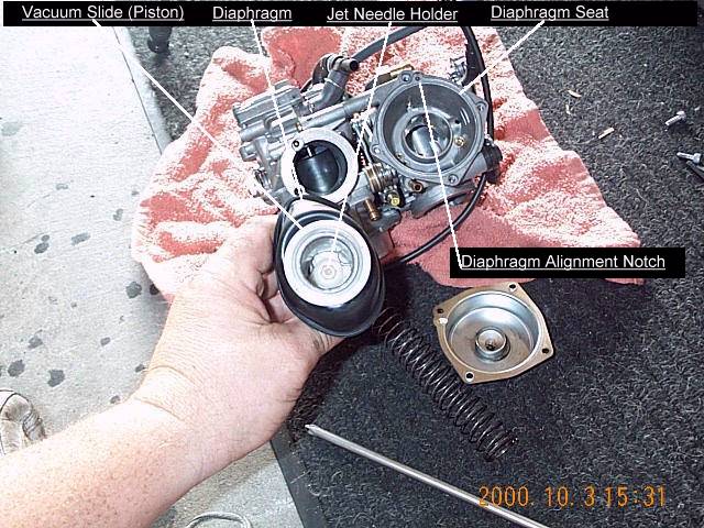
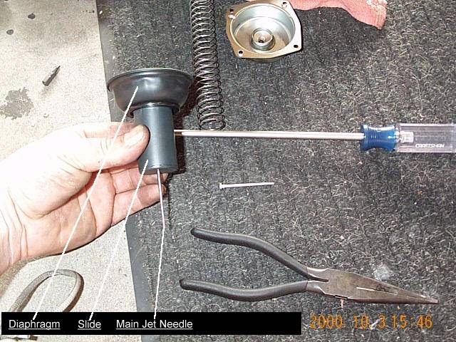
Work one carb at a time. Remove the cover from the vacuum chamber. Do this carefully as there is a large spring holding the vacuum slide down in the chamber. This will expose the vacuum slide that contains your main jet needle. |
 |
|
Remove the vacuum slide. In the bottom of the slide is the jet needle holder. It has a slot for a Phillips head screwdriver in it's top. Carefully turn the holder to the left about a quarter turn to unscrew it. Then tip the slide over to remove the holder and the needle. NOTE: Be very careful not to damage the diaphragm. |
 |
|
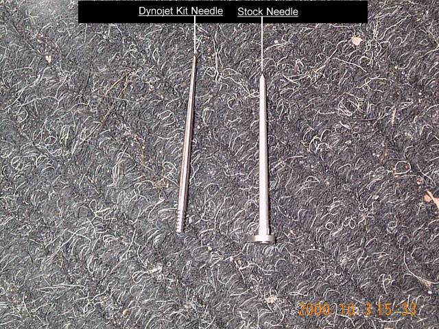
This is a comparison of the stock needle and the kit needle. The kit needle is much thinner and more tapered. This is where a large change in the rejetting occurs. The kit needles will provide a much swifter and smoother throttle response, and a bit more fuel when needed. |
 |
|
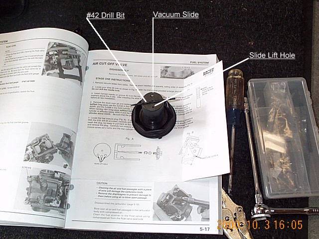
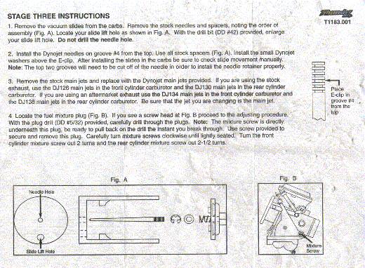
Following the jet kit instructions, use the indicated drill bit to enlarge the slide lift hole. This allows the slide to react more swiftly to the throttle by increasing the vacuum within the slide vacuum chamber. Only drill the existing hole, not any extras. The instructions show more than one as other bikes may have more than one. Ours only has one, so only enlarge the existing hole. However, one forum member reported drilling the slide just as the instructions show (the three arrows, which are indicating your hole may be in any one of the three positions, not ALL THREE) , and reported (at least in the short term, haven't heard anything lately) that it worked fine (pretty much the same as drilling one BIG hole), and there were no adverse effects. DO THIS ONLY AT YOUR OWN RISK! Spirit 750 owners can skip this step as you do not have slide lift holes. You jet kit comes with weaker springs to allow the slides to lift faster. |
 |
|
Following the jet kit instructions, place the e-clip in the indicated groove (the instructions from this kit indicate the 2nd groove from the top) and place the spacer (washer) on top of it. The clip should press on with your fingers. The Stage 3 instructions indicate the 4th notch, but many (like me) find the 3rd notch runs better. When rejetting for the Thunder Air Kit, the needle clips should be placed on the 4th notch (but, see above) as indicated in the Stage 3 rejet instructions. Read the Cutting The Needles page for additional info on this BEFORE you cut the top 2 notches off the needles per the Stage 3 instructions. The first picture shows my clip in the 3rd notch of the needle, which is where I had it for a time before moving it down to the 4th notch (later returned to 3rd notch). The needle has had the first notch cut off, so the needle holder will fit back on to of the needle. This will make it appear that the clip is in the 2nd notch, but that is only because the first notch is missing. As you will see on the Cutting The Needles page, it is not necessary to cut 2 notches off as Thunder recommends. The next picture is a close up of the needle. The next picture shows the clip moved down to the 4th notch, although appearing that it is in the 3rd notch, as explained above. Read the results of my recent Dyno Runs for more information about this. Slide the needle back into the slide and install the needle holder back in place with a quarter turn to the right. I used a pair of needle nose pliers to lower and turn the holder into place, as the holder has a spring on the back that must center over the needle properly. The final picture shows the needle re-installed in the slide. |

|
|
Carefully insert the slide back into the vacuum chamber. To insert it fully, you must guide the slide in so the needle goes through the main jet tube in the bottom of the chamber. I first rolled the diaphragm back down as shown, and started the needle into the jet. Slowly lower the slide while holding and positioning the diaphragm lip in the seat on the chamber. Be careful to seat the diaphragm back into place in the groove with the proper alignment. There is a notch on the groove that corresponds to a small indentation in the diaphragm lip, as shown in the picture. This assures proper alignment of the slide in the vacuum chamber. Carefully re-install the vacuum chamber cover, trying not to disturb the diaphragm seal in the seat. |
|
|
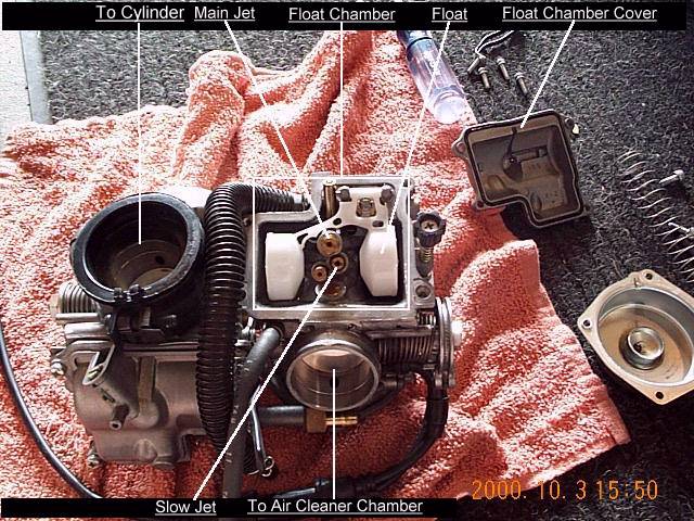
Next, flip the carb assembly over and carefully remove the 4 screws holding the float chamber (float bowl) cover in place. Be careful not to disturb the floats. This will expose the jet you will need to replace. The main jet is screwed into a longer tube that then screws into the carb body, and is known as the emulsion tube. My screwdriver is pointing at the main jet. In this case, it is a Dynojet 106, for the front cylinder, from my last rejet. Carefully unscrew the jet. The emulsion tube it screws into may decide to come with it. If so, let the whole thing come out in one piece, the unscrew the jet from the tube while holding the tube with an open end or adjustable wrench. The top of the tube has flats on it's sides for this. Also shown is the jet removed from the emulsion tube. Note the size of the orifice (the hole in the center). When NOT rejetting for the Thunder Kit, carefully screw in the size jet indicated in the jet kit instructions for your particular intake/exhaust/elevation setup. ***As a matter of note, the kit recommends a 106 in the rear and a 102 in the front for baffled pipes below 4000 feet. The stock jets I removed were stamped 110 rear and 105 front. As many have determined, the numbering from one manufacturer bears no relationship to the numbering of another manufacturer. Also the new jet size is matched to the new slimmer needles. So don't worry about comparing the number from your stock jets to your new ones.*** |
|
|
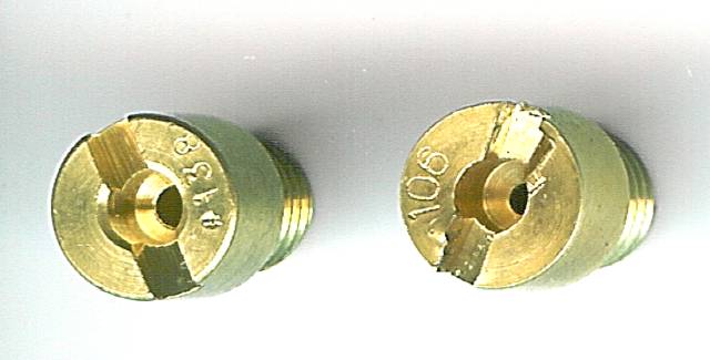
When rejetting for the Thunder Air Kit, do not use the small jet from your jet kit, use the jet that comes with the Thunder Air Kit. This will be a 134 jet for the front cylinder, and a 138 jet for the rear cylinder. I have no information if Thunder provides the 134 & 138 jets with the air kit if you order their jet kit at the same time. I believe their jet kit comes with 134 & 138 jets. In any case, you want the 134 & 138 jets whether they are in your jet kit or with the air kit. For the front cylinder, carefully screw in the 134 jet provided in the kit. Here is the 134 jet installed in the first picture. The second picture is the 106 jet. Note the much larger orifice size. Here is a scan of the 106 and 138 jets. I decided to get a better shot of the orifice size differences and threw them in the scanner because they were the ones not in the carbs. The 106 and 110 are so close, I think you get the idea. Grand Canyon. |
|
|
If you have chosen to replace your stock #40 slow (or idle, or pilot) jets, as I did, remove the slow jet by carefully unscrewing it. Here is an attempt to show the very minute, but important, size difference between the stock #40 slow jet and the larger #42 slow jet. This jet is a stock Aero #42 slow jet. I ordered these from my dealer for about $25 for the pair.
The slightly larger slow jet will allow you to provide sufficient fuel in the off throttle position and keep the mixture screws closed to around the 2 1/2 turns closed region. This leaves you plenty of adjustment room, where the stock #40's often need to be cranked open to as much as 3 3/4 turns open, and there are only 4 turns (one person has reported more than 4 turns of thread available, but I haven't verified that) worth of threads available on the screws. Plus, the slightly larger size will deliver a slightly higher volume than the #40's can provide. Since you are going to be in here anyway, it's a convenient time to replace these now rather than later. The #42 is on the left, and the stock #40 is on the right. Carefully re-install the float bowl cover. |
|
|
Repeat all the above steps on the OTHER carb. EXACTLY as shown in the accompanying illustration! (You AREN'T really DOING that, ARE you?!?) |
 |
|
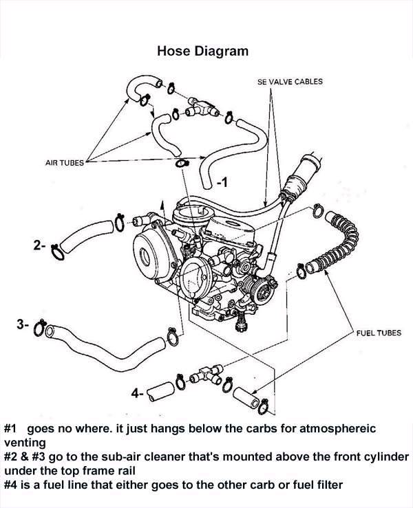
Now read some tips to keep you from throwing your best tools across the garage in a fit of rage. When reinstalling the carbs, a bit of ingenuity is required to route the hoses back where they belong, and not forget any hoses. Reseating the carbs on the boots in a cinch now, just insert the carbs in the bike, re-install the right intake boot, then carefully slide the carbs down into the boots on the cylinder intakes. After you put all that stuff back in, make sure you pull out and push in your choke knob a few times to get the cables back in shape, before you try to start it. I guess now is a good time to mention that a.v. hose again, like I said I would. A number of people find one hose left over, as I did the first time, and don't know where it goes. I spent quite a while looking over my pictures, and finally realized what it was. It has now become known as the "Atmospheric Vent Hose". On the Cal bikes, it comes off the bottom of the EGR valve, runs around the front of the front cylinder, to the right, and hangs down on the right rear of the cylinder. It's there to suck air. Here's a couple pics from my most recent rejet. That's the a.v. hose coming from the bottom of the EGR valve. On the 49 state bikes, it comes of a "T" on the top of the carbs and does much the same, but on the left side. Forum member Nicebadboy labeled this scan from the service manual and sent it to me, and this will show the 49 state bike setup. Somebody else sent me one awhile ago too, but I can't find it. Now, remove the rags and reinstall the carbs, air cleaner chamber, plug all the hoses back in and hook your choke back up by reading backwards from this point, then hyperwarp back to this point to learn how to fiddle with your mixture screws. When installing The Thunder Kit, don't reinstall your stock air box (duh…), just stuff the carbs back in the bike like you threw them to the garage floor earlier, then go to the bottom of the page for your "break" and the link to the payoff for all this hard work. You can play with your screws later. |

|
|
The final step to complete your rejetting is to adjust the idle mixture screws. If yours are still plugged, follow the instructions with the jet kit to remove them then adjust the mixture screws as indicated. The kit comes with a drill bit and screw for this. You can also follow the instructions on my Adjusting The Mixture Screws page. When installing The Thunder Kit, and you are doing a full rejet, follow the directions with the jet kit for adjusting the mixture screws, and find the bottom of this page to continue. The instructions indicate to set the mixture screws to 2 1/4 turns out on the rear and 2 turns out on the front. Sorry Dynojet, too lean. I had quite a bit of popping and backfiring on decel. I put them back where I had them at 3 1/2 on both and that eliminated almost all of the popping. I still have a small number of quiet pops on decel occasionally, but it's liveable. If you have installed the larger #42 slow jets, about 2 1/2 turns is a good place to start with both screws. It took about 30 seconds of cranking, in 10 second intervals, to get fuel back into the line and into the carbs. Don't forget to turn your fuel switch back on! There is a noticeable increase in power that I would put somewhere around 10%, but that's a seat-of-the-pants measurement. What is most noticeable to me is the added low end torque. The bike pulls much harder in all gears, but it is really noticeable in the low end of the power band in each gear. I think I got back some of the lost torque from the sprocket change. Roll-on at mid-range is also much better. Getting from 60 to 80 happens much quicker now, and 5th gear has pull that it didn't have before. All of the gears can pull at lower rpm now than they could before. The bike runs MUCH better and runs much stronger. Well worth the investment of time and money. |
|
|
When installing the Thunder Kit: At this point, without messing with my screws, I fired my new firebreather up. With those big jets, she runs (not on the road, in the garage!) quite well without the filter. I wanted to make sure I had everything right before I went about mounting the Thunder Kit. Everything was great. Make sure you crank the engine in short bursts, about 10 seconds or so, while giving it a tiny bit of throttle in tiny little wraps to get fuel back into the carbs. After abut the 3rd crank, she'll start to fire up. On the 4th she should start and idle. Let it run for about 30 seconds, then give it small amounts of throttle slowly. If it seems okay, it IS okay. Shut her down and move to the next step. |
|
|
Well, only one more step left. You'd better take your last break before we move on to the payoff! |
|


