| Thunder Charged! Part 1 The Rejetting -Teardown |
|
Due to some confusion about whether to buy a jet kit along with a Thunder Air Kit: If you have previously rejetted your bike (for pipes, etc.) you DO NOT NEED to purchase the Thunder Jet Kit when you purchase your Thunder Air kit. The Thunder Air Kit will include new main jets, 134 & 138 to replace the main jets you have in place now. You MUST install these larger jets. You will pull the carbs and install the larger main jets and adjust you needle clips ONLY, as indicated in Part Three of this procedure. If you have not previously rejetted your bike, you WILL NEED to purchase the Thunder Jet Kit when you purchase your Thunder Air kit, as you will need the new needles, and the correct drill bit for drilling out the slide lift holes on your vacuum slides. You will pull the carbs and follow ALL THE STEPS as indicated in Part Three of this procedure. In Part Three you can also read the updated information about dropping the needle clips when adding the Thunder Kit to a previously rejetted bike, and view the results of my Dyno Runs. Also, here are scans of an excellent CV Carb Tuning sheet that Bamm (Bamm Motorsports) gave me. Bamm Motorsports, the Official Speed Shop of SA750, has done my dyno runs and helped with my engine tuning. Tuning1.jpg Tuning2.jpg |
|
NOTE: For those who really like the stock air box, and want to do something with it to increase performance, you can follow Bean's lead and modify the stock air box and install the new K&N filter for the stock box, along with the proper jetting for that airflow. It's nowhere near the power & performance of a 360 degree open K&N thunder Kit, but it is a significant increase from stock or standard stage 1 jetting. For info on this, see the Stock Air Box Snorkel Mod page. For my thoughts on the performance and value of a Thunder Air Kit, see the last section of this page, Part 4. |
|
I finally decided to break down and buy a Thunder Air Kit. I purchased it from Paolo at Hellriser Customs. Paolo is a nice, helpful guy, and has awesome prices on ACE 750 stuff, like the Thunder Air Kits. I chose the round kit with "Thunder Charged" on the cover. The round kit is $195 from Hellriser's. Check around and see if you can beat that price! I did not have to order a jet kit as I have previously rejetted. I only need the 134/138 Stage 3 jets that come with the Air Kit. What's a Thunder Air Kit? Well, it is a custom machined backing plate to replace the stock air box, allowing you to attach a high flow K&N air filter, and top it with a custom machined cover. The kit replaces the entire stock air box. The point of all this being, with a K&N air filter your beast can now suck in more air than you can imagine. Team all this intake air with the much larger main jets that come with the kit, and the result is a large and dramatic increase in power and response. The combination of a performance aftermarket exhaust (like my V&H Cruzers), a Thunder Kit, and rejetting the carbs but using the huge main jets that come with the Thunder kit instead of the much smaller mains that come in a jet kit, will yield a 10 to 20% power increase depending on your individual setup. Different Thunder Kits flow more air than others. The 360 degree open kits, like the round kit I chose, provide the biggest boost. Below you will find a disturbingly detailed set of step by step instructions on installing a Thunder Air Kit, and Rejetting. I had previously rejetted when I added the Cruzers over a year ago, so I only had to change out the main jets. This time I took all new pictures of the procedure, covering every move. A much better set than I originally did for the rejetting page. So good, in fact, that I have combined some of the pictures and instructions from the original Rejetting page into this page for a full rejet, and this page will now be the full blown, end it all, Official SA750 Rejetting Page! Before we start, let me make two statements: NO SMOKING!!! The reason should be obvious. We are playing with gasoline and your bike.
LABEL YOUR HOSES!!! Too many people can tell you about the hours they spent trying to figure out where they all go back. Some additional info: Jetting Considerations For Motor Performance Factors Part Five contains a table of scans from the Service Manual covering Section 5 – Fuel System, along with scans of the jet kit instructions and the label from inside my left side cover showing the vacuum hose routing. That being said, follow along, and have fun. I did! Steve
|
Click on a Thumbnail to Enlarge
|
The first step is to remove your front seat. I didn't take pictures of this since I figure you're all sharp enough to figure out the two bolts to accomplish this! |
 |
|
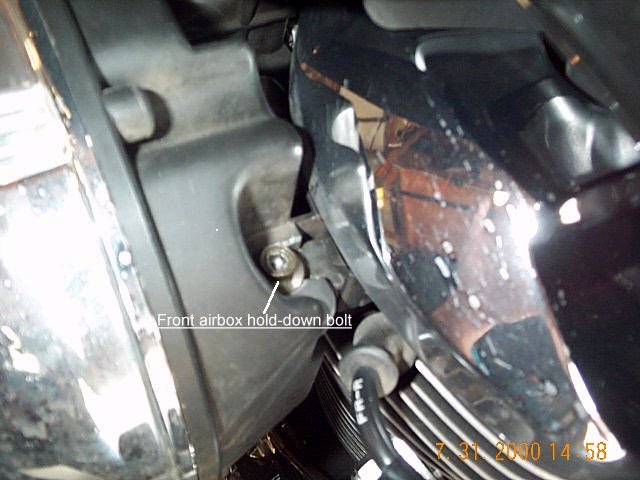
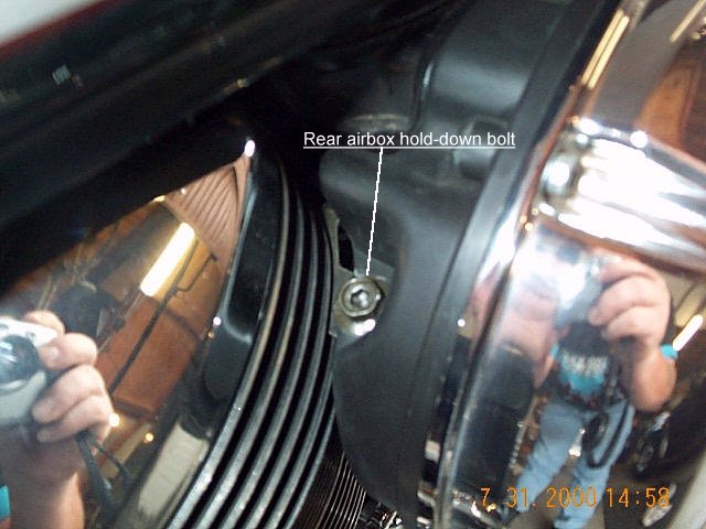
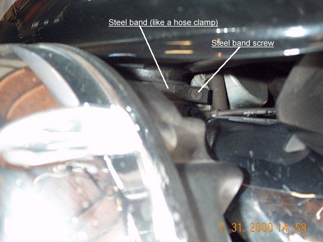
Next, remove the stock air box. On the back side of the air box, on the front and rear (looking down from the tank) you will see two hex bolts with allen sockets in them. Use the allen wrench in your bikes tool kit to loosen these (they don't need to be removed), or a ratchet with a 10 mm socket. The heads are about 1/2". You can't miss them. Now look behind the air box, on the right side near the top. There is a steel band that is tightened around the intake tube that leads from the air box to the air cleaner chamber. Loosen the screw on the band. Now just pull the air box toward you and down and remove it. When you remove it, set it aside somewhere safe because you will need it again in a later step. |
|
|
Stock air box removed and set aside in a safe place for a later step. You will remove the rubber intake boot to use on the Thunder Air Kit. |
  |
|
Remove the mounting bolt from the rear of the fuel tank so you can remove it quickly after unplugging the fuel line. It is best to set up a place with a towel, and a small box about 6 inches high to put the tank once you remove it. Turn your fuel petcock to the "Off" position, then remove the fuel line from the petcock. Have a rag handy as some fuel will leak when removing the the fuel line. The petcock will sometimes dribble as well. Hold the rag over the petcock as you lift and remove the fuel tank. Place the tank on the towel with the rear end of the tank resting on the box. This keeps the petcock higher than the fuel so it will not leak. |
 |
|
Remove the tank vent line from the right rear of the fuel tank. Now is a good time to check if it is clear, and not plugged up, by blowing through it. Air should move freely through it. Why do this? Because a couple of forum members have had their tanks implode from a plugged tank vent. As fuel is pulled from the tank, air must be able to enter the tank to replace the fuel. If it can't, the tank develops a vacuum that will cause your tank to suck in on itself until it collapses. Needless to say, it ain't pretty. And it ain't cheap either. So quit arguing and go suck on your tank vent………….NOW! |
 
|
|
At this point, if you were doing a full rejet, it would be about time to drain the carb float bowls. I did not drain them this time. I'll explain later how you do this after you remove the carbs. If you want to drain them now, attached a length of vinyl tubing to the drain nipple, then open the drain screws and let the fuel empty into a plastic or glass container. Toss the fuel when you're done. While we have the seat off, I thought I'd stop for a moment to say that black box under the seat is your ICM, or Ignition Control Module. This is the thing a few have replaced with a Dynatek ignition, allowing you to change the timing and raise the cutoff level for the rev limiter. It's a performance thing! Hellriser Customs now sells the Dyna 3000 module for the ACE 750. Lastly, damn it gets dirty under there! |
|
|
Next remove the choke knob assembly. With the allen wrench in your bike's toolkit, remove this bolt, which holds the choke knob bracket and the cylinder fin. Slide the arm out from behind the cylinder fin.
If you have a carb cover, such as the Pro 1, remove it from the choke knob assembly so it does not get damaged when you pull the choke cable between the cylinders when removing the carbs. |
  |
|
Now it's time to unfasten the throttle cable mount assembly. There are two Phillips head screws that hold this bracket in place. Why do I have one flat and one Phillips? Because the first time I removed it long ago the head stripped so I replaced it with a flat. They are tight so make sure you apply good pressure as you loosen them so you don't have to have two screwdrivers for this like I do! |
 |
|
With the bracket loose, this provides the needed slack in the throttle cables to remove the barrel ends from the throttle wheel. Pull the cable around to the back of the wheel so it's in line with the slot and carefully work the barrel out if it's slot. Remove both barrel ends, then let the assembly hang free out of the way. |
  |
|
The California bike has additional hoses not mentioned in the Service Manual, but are referenced with the pic on the label inside the left side cover. You can purchase a book of wire markers from your local hardware store that will make the labeling easy. Label each hose with a number, and the corresponding nipple with the same number. You don't have to follow my numbering, since there's no rhyme or reason to it. Just make sure each hose has a unique number. If you have a digital camera or a Polaroid, you might want to take pictures too. They might come in handy later. While we're here, for those with California bikes, lets start by unbolting the EGR valve. Now is a good time to label the hoses we are going to pull from the EGR valve, as shown here. Label the hose, and the nipple it corresponds to. Now pull the two labeled hoses. Hose #1 connects to the side of the EGR valve right under the "3" label on the flange on the valve. The hose that connects to the bottom of the valve is the infamous "atmospheric vent" hose that runs across to the right side front cylinder and hangs right down the rear of the cylinder. This is the hose that many have "left over" after putting everything back together, and can't figure out where it goes! When the two labeled hoses are disconnected, pull easily on the EGR valve and that will pull the a.v out. Take note of how it's snaked through as you pull it out so you can weave it back much the same way when you get done. If you have a 49 state bike, you have no EGR valve (smog stuff), so you can skip this. But your atmospheric vent is a hose connected to the "T" on top of and between the two carbs. One hose on that "T" goes to one carb, the 2nd hose to the other carb, and the loose hanging one is your a.v. hose. More on that later. |
|
|
Still on the left side, label and pull this hose from the carb. It runs forward to the air pre-filter that sits on top of the front of the front cylinder. There is another on the right side, just like it. You can run over there and go find it now if you want, or you can stay with me here and we'll be over there in a minute. |
 |
|
If you want a little more room, you can remove the front ignition coil. Unplug the two wires going to the coil. Make note of the color of the two wires so you can plug them back in correctly. The white wire goes on top. Then remove the two bolts holding the coil to the frame.
This is an update from my last jetting changes. Subsequent pictures may show the coil still attached. |
  |
|
Now loosen the band clamp on the intake tube that runs over to the air cleaner chamber on the right side. By the way, that yellow zip tie is holding down the cover on the air pre-filter I talked about. This cover comes loose quite easily, and will cause the bike to idle and run poorly. It's due to the design of the box. the cover just clips on ans the clips sometimes don't want to hold. that's why i used the zip tie. Now's a good time to check yours! I pulled mine out on the last rejet, to clean the element inside. It's just a small piece of foam. Here is a pic of the prefilter assemmbly removed, and a bad pic of the cover removed. Move to the right side where the air cleaner chamber is and loosen the band clamp on the right intake tube. Carefully work each one loose by lifting and jiggling the tubes close to the carb intakes where the connect. Then carefully pull the air cleaner chamber and the intake tubes free of the bike. Be careful as you do this so you don't pull the intake tubes out of the air cleaner chamber! Part way out you will be able to access this hose on the rear of the air cleaner chamber. Label it and the a.c.c (got tired of typing air cleaner chamber…D'oh!), and continue to pull the a.c.c free. "Captain of the Boat, make your depth five zero feet! Up Periscope!" Okay, I think we both need a break before we continue on to part 2. So relax for a moment and click here. If you are a lady of the female persuasion, relax for a moment and DO NOT click there! |
|


